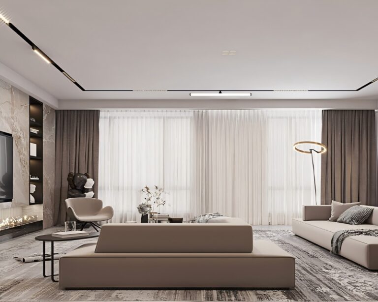
Read the rail as infrastructure
Its profile, mounting detail and electrical interface influence every luminaire attached later. Draw the complete route through corners and terminations before considering a decorative module layout. Trace the route as a sequence of real parts: a feed, the first rail, a junction, the next section and its termination. Where the line crosses a ceiling joint or turns onto a wall, enlarge the detail instead of extending the same pen stroke. The physical joint may need support even when the lighting plan shows uninterrupted darkness. Identify the rail family beside each route, especially where a project uses more than one system. This prevents the apparent continuity of an architectural drawing from becoming an assumption that all rails share an interface. Procurement should be able to count the sections and identify their junctions directly from that drawing.
Understand retention and power
Magnetic attachment holds the luminaire in position, while conductive contacts provide the electrical connection. Mechanical fit and electrical suitability are separate checks when choosing replacement or additional heads. A head that appears to hold in a rail has not yet passed the electrical selection review. Contacts, adapter geometry and the chosen power arrangement must match the intended assembly. Keep the power isolated during installation and follow the instructions for insertion and removal of the selected products. For a later replacement, send the recorded rail designation and photographs of the adapter rather than asking only for a magnetic lamp. A close visual match can hide a different interface. Where a buyer is considering a substitute, ask for the substitute to be identified in the component schedule, with its connection requirements reviewed before any assumption of compatibility reaches the site.
Build a lighting hierarchy
A rail can carry different optical functions within its own compatible range. Use broad illumination for orientation and directed light where a task, artwork or merchandise display needs more attention. A reception counter needs useful light on the work surface and on the person approaching it; an accent aimed only at the wall behind may leave both poorly served. Draw those jobs separately before choosing bodies. In a display area, broad background illumination can hold the room together while selected spots emphasize a changing exhibit. Grilles add their own visible pattern overhead, so their rhythm should agree with the architecture without forcing equal spacing on unequal tasks. Review mirrors and glazing alongside the target surfaces. The optical hierarchy is incomplete if the intended accent also creates the brightest distraction in a visitor's normal view across the room.
Coordinate installation depth
The visible rail line tells only part of the story. Recessed profiles need room within the construction, and suspended rails need a relationship with the structural fixing points above. A recessed section needs space for its body and a fastening detail, not merely an opening wide enough to show the dark slot. Include the surrounding ceiling build-up, backing and any services passing above. For a suspended route, dimension from the finished floor or another stable architectural datum rather than from an unfinished slab with changing levels. Draw the lowest position of adjustable lamps as well as the rail itself. A fixture that looks flush in a closed product image may project into the room when aimed. This assembled section is what the architect needs when checking a low doorway, a tall cabinet or a route beneath ventilation equipment.
Locate serviceable components
A clean ceiling is easier to maintain when supply and connection positions are intentional. Keep access practical rather than hiding every electrical part behind a permanently finished panel. Mark the access route with the room in its finished condition. A removable ceiling tile is useful only if a shelf, partition or suspended fitting will not prevent it being lifted later. A connection hidden behind fixed decorative panels may demand destructive access when a cable or supply needs attention. Coordinate the locations with the electrical contractor and the joinery installer rather than allowing each trade to reserve the same small void. Label the appropriate isolation point in the maintenance information. The goal is an identifiable electrical arrangement whose components can be reached in accordance with their instructions, while the rail retains the clean appearance that motivated its selection.
Specify control as a combination
A controller, receiver and luminaire should be chosen as a working set. Describe the desired daily actions, such as group switching, before asking for the particular device arrangement. Write the desired actions in ordinary room language before assigning device names. Reception lights may operate with the entrance, display accents may need their own group, and a meeting area may need a different evening setting. Transfer those actions onto a control plan and have the proposed controller, receiver and luminaires identified against it. A communication label does not establish that every device carrying that label will work together. Keep the model descriptions and any commissioning instructions with the accepted proposal. Staff then inherit a way to operate the room, while the contractor has a defined combination to install rather than a loosely described ambition for smart lighting.
Document future changes
A useful handover drawing identifies the rail family, module descriptions and connection points. That information makes later reconfiguration more predictable than relying on a photograph of the finished ceiling. Store the accepted rail cross section, luminaire descriptions, mounting arrangement and electrical diagram together, with revisions dated consistently. Add a marked elevation showing the targets of adjustable heads. The spare-parts record should distinguish a lamp change from an accessory change, because a replacement input or corner raises different questions from an extra spotlight. Photograph labels before packaging is discarded and attach them to the project file. If an installer substitutes a component, update that file while the substituted item can still be identified. A later buyer can then describe the actual installation instead of reverse engineering it from a dark ceiling photograph and an old quotation title.
Bring the selection into the room: Magnetic Track Lighting System Architecture
Review the system from the incoming connection to the last lamp, with the ceiling section beside the plan. Every rail junction needs a physical explanation, and every electrical component needs a place and an access route. Retain the accepted assembly as a project record when the order is placed. That record will support later additions far more effectively than a general instruction to buy another magnetic track light.