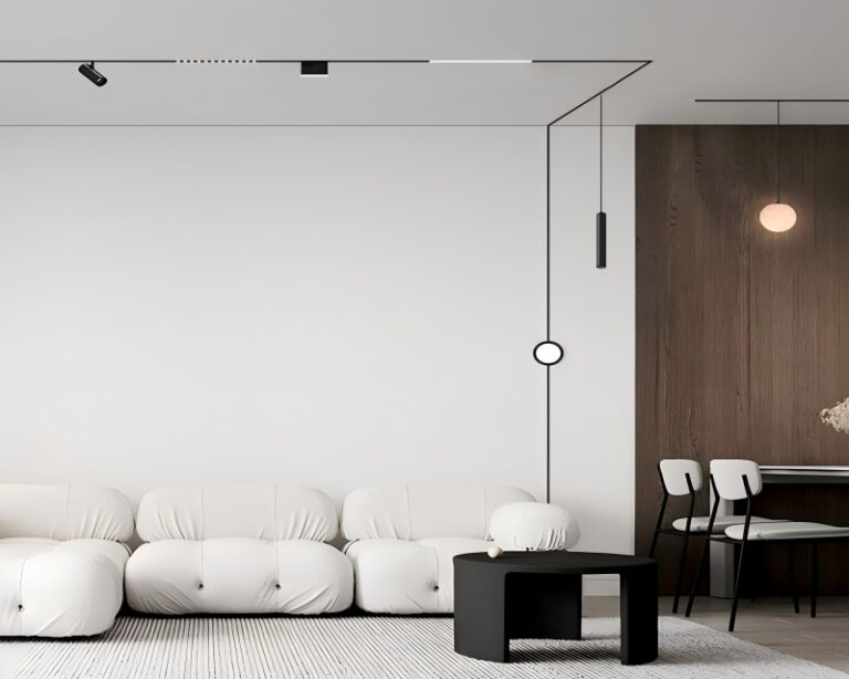
Understand what ultra-thin describes
The slim dimension belongs to the YZ-M26A rail body. Attached luminaires, connections and supply components create the final assembled silhouette and should appear in the room section. The 26 × 6mm dimension makes YZ-M26A a very shallow surface body, but it should not be used as the installed depth of an M26 lighting scheme. Put the selected grille, flood or projecting head beneath the rail in the room section. Add the input location and any corners that remain visible. A low ceiling can benefit from the restrained line while still being affected by a hanging lamp or an aimed cylinder. Check the view from seating as well as from the entry. The buying decision should protect the overall headroom and appearance that motivated the thin rail, rather than judging every component against the bare strip alone.
Match the profile to the ceiling
A surface body, a winged recessed section and a deeper suspended section solve different construction problems. Choose the correct rail form before refining the luminaire mix. Choose surface mounting where the rail is intended to sit visibly on the finished surface, and review a recessed section where the ceiling construction is designed to receive it. A deeper suspended form needs an agreed level and support arrangement. The soft-membrane option introduces a dedicated ceiling edge rather than simply another way to hide aluminum. Draw each mounting condition with its surrounding material and identify any transition between them. A family name can tie the options together without eliminating their construction differences. Give the installer the selected profile designation, not just an instruction to use thin M26 track, so its fixing, finishing and joining parts follow the actual section being purchased.
Keep the optical choices open
M26 includes linear grilles, floods, spots, folding fittings and decorative forms. Start with the lighting tasks and then choose shapes that keep the ceiling composition coherent. Use the room's targets to edit the M26 lamp range. A linear flood can provide a broad luminous face, a grille creates repeated cells, and a spot introduces an aiming direction. Folding fittings change their silhouette when positioned for work, while decorative forms can establish a local feature below the ceiling. Place those bodies in elevation before deciding on their rhythm along the thin line. Empty rail can preserve visual calm where no optical task is needed. A quotation with every module assigned to a surface or activity is easier to refine than a uniform row chosen to fill the available length. Keep the intended role beside each model in the enquiry.
Resolve corners as components
Horizontal, vertical and curved joining directions need their own parts. Show the intended turn in elevation where a track moves from ceiling to wall or changes level. A horizontal turn seen in a reflected ceiling plan differs from a rail continuing onto a wall. Show the latter in elevation, including the point where its plane changes and the orientation of the attached lamps. Where a curved joining direction is proposed, identify the matching components instead of drawing a sharp corner and leaving the geometry to procurement. Corners can also affect the position of nearby feeds and mechanical supports. Keep those parts visible in the section schedule and check the order of assembly before finishing begins. The apparent continuity of a slim rail is an architectural result made from selected fittings; it is not evidence that the same connector can serve every turn.
Plan the driver-fed arrangement
M26 power components include DC48V supplies and input modules. Coordinate the power location and access with the rest of the reflected ceiling drawing. Locate the DC48V supply where it can be reached after the room is complete, then draw the route to the selected M26 input module. A shallow visible rail does not remove the separate space and service needs of its power arrangement. Have the electrician review the actual connected lamp ratings and the equipment instructions. If the design adds decorative bodies or more broad-light modules, update the load schedule rather than assuming the unchanged rail length leaves the electrical design unaffected. Mark access beside other ceiling services on the coordination drawing. Concealing the supply can preserve the thin architectural line, provided that concealment still allows a practical maintenance route and appropriate installation conditions.
Look beyond the rail thickness
In a low room, a projecting spotlight or hanging shade can influence perceived headroom more than the slim rail itself. Compare installed depths from the main viewing positions. A low room often exposes the underside of its lights to people sitting nearby. Check whether a spotlight can be aimed at the target without presenting a distracting optical face toward a sofa or bed. Draw pendant bodies against door heads, tall storage and the circulation path. Even where the rail body is shallow, a decorative lamp can occupy a much more noticeable band of space. Compare the complete arrangement with the furniture installed, not against an empty ceiling photograph. If the composition needs fewer projecting elements, adjust the optical mix intentionally rather than relying on the rail's ultra-thin description to carry the whole promise of a restrained installation.
Send a complete M26 inquiry
Include the intended profile, room dimensions, lighting functions and preferred finishes. Request the corresponding component schedule so a thin architectural line becomes a workable installation. Identify the rail profile and use the listed 1000, 1500 and 2000mm lengths when preparing the initial takeoff. Mark proposed junctions so the accessory request follows actual pieces rather than a continuous drawn line. Add room dimensions, ceiling construction, finishes, target surfaces and the intended lamp forms. Request the DC48V supply and input arrangement alongside the rail and lights. Where the final profile remains open, ask for separate section proposals rather than an unspecified M26 package. A dimensioned plan with a constrained ceiling section lets the quotation address the thin visible line, its attached bodies and the hidden equipment as one installation that can be reviewed before ceiling work is committed.
Bring the selection into the room: M26 PLUS Ultra-Thin Magnetic Track
Keep the YZ-M26A rail dimension beside a section of the complete M26 assembly. Select the mounting profile, then add lamps, corners, feeds and the DC48V supply location. Use the available profile lengths to make the first section takeoff and identify any ceiling-to-wall change in elevation. Send that drawing with the intended lighting tasks so the thin rail is priced as a buildable room scheme, including the parts that give it light and power.